An automotive obd scanner diagnostic analyzer, also known as a car diagnostic computer, can easily plug into an automobile's computer system in order to read the codes installed for each car's on-board computer. However, not every car diagnostic computer is the same. Check the model that you have purchased -- or are considering purchasing -- is compatible with your vehicle. Car diagnostic computers are useful to have in your toolbox since a lower-end model can cost less than $100, which is comparable cost-wise to having your car scanned at a service center.
1. Open the driver's side door of your car. Since 1996, vehicles produced for the American market have utilized a standardized On-Board Diagnostics (OBD) system. This means that every car manufactured since 1996 is readable by most diagnostic analyzers used by professional mechanics as well as those available to consumers. The D-style, plug-in connector for a diagnostic analyzer is usually located underneath the driver's console in or around the fuse box. Refer to the owner's manual for your vehicle to help locate the plug-in connector for the scanner.
2. Turn on the diagnostic car scanner and plug it into the D-style plug-in connector. Follow the prompts on the scanner and press the "Check" button. Different scanners will operate with slight variations. Turn the key in the ignition to the "Accessories" position. Wait two to five minutes for the scanner to read the code(s) displayed by the car. Some lower-end scanners may require you to connect the scanner to a computer via a USB port. According to CarsDirect.com, a Palm Pilot will often work to help read the code from the scanner.
3. Look up the diagnostic trouble code on the Internet if your code reader does not have the ability to display the problem. Some scanners that are more expensive will be able to tell you what the problem is as well as the code that goes along with the problem. gm tech 2
4. Clear the code from your car after making the necessary repair. If the codes or a "Check Engine Light" reappears after driving the vehicle a few miles, the problem has not been resolved and will need to be looked at again.
UK SHIP, NO TAX

Monday, 30 June 2014

Thursday, 26 June 2014
How to update maxidas DS708
First, should be have original Autel Maxidas DS708 Automotive Diagnostic System, PLS buy original DS708 Automotive Diagnostic System
When you connect DS708 with your car(power) at first time,
There will be an menu interface, and tell you the serial number and password about
Your DS708(just unique), pls save them!!! it is the key when updating!
then use the serial number and password, register a user name:
http://www.maxidas.com/member/service.aspx
after finished, you can download the latest versoin DS708 file,and uninstall the old version
install latest version to CF cards.
When you connect DS708 with your car(power) at first time,
There will be an menu interface, and tell you the serial number and password about
Your DS708(just unique), pls save them!!! it is the key when updating!
then use the serial number and password, register a user name:
http://www.maxidas.com/member/service.aspx
after finished, you can download the latest versoin DS708 file,and uninstall the old version
install latest version to CF cards.
Thursday, 19 June 2014
How to solve Honda CR-V and ABS communication failure
Honda CR-V 2 2007. 4L car with mileage about 97,000 km, whose ABS indicator light flashes intermittently. But after carried ABS road test, it is found that the ABS system is working properly.
Diagnosis:
1) Apply Honda HDS HIM to read the fault code, indicating DTC BL170--communication fault between instrument control module and ABS modulator control unit.
(NOTE: HDS is a powerful and affordable Honda diagnostic tool It is available for reading and decoding fault codes from control blocks memory. For more information, click here: http://www.obd365.com/wholesale/honda-hds-him-diagnostic-tool-with-double-board.html)

2) Disconnect the pin B (36 cores) of instrument control module connector and the 26-pin of ABS modulator control unit.
3) Use a multimeter (such as: MST-2800B Intelligent Automotive Digital Multimeter) to check terminal communication lines of 26-pin ABS modulator control unit and B-pin (36 cores) instrument control module connector. The result was that communication control lines were functioning.

4) As the figure shows, use a multimeter to check communication lines connecting 26-pin terminal of ABS modulator control unit and B-pin (36 cores) terminal of instrument control module connector, indicating that the communication control circuit is working. So it can be inferred that ABS modulator control unit has no problem.
5) According to the phenomenon, it can be determined as intermittent defect, which is usually caused by poor contact of bonding or plugs. Looking over the circuit diagram, the main bonding is G401, which tends to be normal. But the direct relevence with bonding is liquid level switch.
6) Finding that the braking fluid level is too low to turn off the liquid level switch, leading to disconnect the G401. As a result, ABS indicator light flashes intermittently.
7)After testing the liquid level switch, it works abnormally. Then change the liquid level switch and add braking fluid, the fault is completely cleared.
http://www.obd365.com
Diagnosis:
1) Apply Honda HDS HIM to read the fault code, indicating DTC BL170--communication fault between instrument control module and ABS modulator control unit.
(NOTE: HDS is a powerful and affordable Honda diagnostic tool It is available for reading and decoding fault codes from control blocks memory. For more information, click here: http://www.obd365.com/wholesale/honda-hds-him-diagnostic-tool-with-double-board.html)
2) Disconnect the pin B (36 cores) of instrument control module connector and the 26-pin of ABS modulator control unit.
3) Use a multimeter (such as: MST-2800B Intelligent Automotive Digital Multimeter) to check terminal communication lines of 26-pin ABS modulator control unit and B-pin (36 cores) instrument control module connector. The result was that communication control lines were functioning.
4) As the figure shows, use a multimeter to check communication lines connecting 26-pin terminal of ABS modulator control unit and B-pin (36 cores) terminal of instrument control module connector, indicating that the communication control circuit is working. So it can be inferred that ABS modulator control unit has no problem.
5) According to the phenomenon, it can be determined as intermittent defect, which is usually caused by poor contact of bonding or plugs. Looking over the circuit diagram, the main bonding is G401, which tends to be normal. But the direct relevence with bonding is liquid level switch.
6) Finding that the braking fluid level is too low to turn off the liquid level switch, leading to disconnect the G401. As a result, ABS indicator light flashes intermittently.
7)After testing the liquid level switch, it works abnormally. Then change the liquid level switch and add braking fluid, the fault is completely cleared.
http://www.obd365.com
Thursday, 12 June 2014
How to solve Toyota P0031 & Check Engine Light on
The Toyota Camry came back again for reparation, which had been repaired
for several times because the CEL was on. Strangely enough, the car
works well without other abnormalities.
Facing this thorny issue, this time I tended to apply V2014.6 Toyota Intelligent Tester 2 IT2 with Suzuki, the SUZUK company professional diagnostic tool for the Suzuki car. I first connected IT2 into the Powertrain / Engine and ECT / DTC, reading the error code P0031 (HO2S heater control circuit low), while the DTC's frame data found no error. According to the maintenance manual, the causes of P0031 are: A / F sensor heater circuit broken; A / F sensor heater (sensor1) fault; engine J/ B (EFI relay) fault; ECM failure, etc.

1) I disconnected C15A / F sensor connector to measure resistance of C15-1 and C15-2 terminal ( A / F sensor heater + B and HT terminals), reaches 2.6Ω, within the normal range (1.8 ~ 3.4Ω); moreover, resistance between C15-1 (HT) and C15-4 (AF-) terminals is infinite, normal. So A / F sensor failure can be excluded.
2) Then I turned on the ignition and measured voltage between the C15-2 (+ B) terminal and the bonding, which is 12.7V, normal. This will initially rule out the A / F sensor circuit fault.
3) According to the system circuit diagram, the resistance between C15-1 (HT) terminal and ECM C24-109 (HAlA) is 0.24Ω, and between C15-1 and the bonding is infinite, indicating that A / F sensor heater with ECM lines is normal. Considering that the fault occurred intermittently, I cleared the code and tested, however, CEL lighted again when the vehicle was driven on a relatively bumpy road.
4) Back to the shop, I found the code was still P0031 re-read by car diagnostic tool IT2. Then I entered Utility (Tools) / CheckMode, which will transfer ECM from normal mode to check mode, afterwards, shaking relevant components. When shaking J / B, CEL light up again. It turned up in several tests, so it can be determined as the J / B-related failures.
Finally, I removed J / B and pulled 1E, the plug was found in corrosion. Combined circuit diagram, 1E-7 is the very power line of A / F sensor heater. I dealt with the corrosion, the fault was completely cleared after repeated test.
http://www.obd365.com/wholesale/digimaster-3-digimaster-iii-original-odometer-correction-master-with-980-tokens-2253.html
Facing this thorny issue, this time I tended to apply V2014.6 Toyota Intelligent Tester 2 IT2 with Suzuki, the SUZUK company professional diagnostic tool for the Suzuki car. I first connected IT2 into the Powertrain / Engine and ECT / DTC, reading the error code P0031 (HO2S heater control circuit low), while the DTC's frame data found no error. According to the maintenance manual, the causes of P0031 are: A / F sensor heater circuit broken; A / F sensor heater (sensor1) fault; engine J/ B (EFI relay) fault; ECM failure, etc.

1) I disconnected C15A / F sensor connector to measure resistance of C15-1 and C15-2 terminal ( A / F sensor heater + B and HT terminals), reaches 2.6Ω, within the normal range (1.8 ~ 3.4Ω); moreover, resistance between C15-1 (HT) and C15-4 (AF-) terminals is infinite, normal. So A / F sensor failure can be excluded.
2) Then I turned on the ignition and measured voltage between the C15-2 (+ B) terminal and the bonding, which is 12.7V, normal. This will initially rule out the A / F sensor circuit fault.
3) According to the system circuit diagram, the resistance between C15-1 (HT) terminal and ECM C24-109 (HAlA) is 0.24Ω, and between C15-1 and the bonding is infinite, indicating that A / F sensor heater with ECM lines is normal. Considering that the fault occurred intermittently, I cleared the code and tested, however, CEL lighted again when the vehicle was driven on a relatively bumpy road.
4) Back to the shop, I found the code was still P0031 re-read by car diagnostic tool IT2. Then I entered Utility (Tools) / CheckMode, which will transfer ECM from normal mode to check mode, afterwards, shaking relevant components. When shaking J / B, CEL light up again. It turned up in several tests, so it can be determined as the J / B-related failures.
Finally, I removed J / B and pulled 1E, the plug was found in corrosion. Combined circuit diagram, 1E-7 is the very power line of A / F sensor heater. I dealt with the corrosion, the fault was completely cleared after repeated test.
http://www.obd365.com/wholesale/digimaster-3-digimaster-iii-original-odometer-correction-master-with-980-tokens-2253.html
Wednesday, 28 May 2014
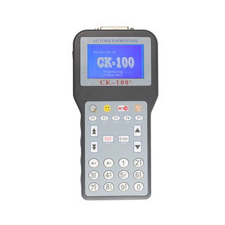
CK-100 Auto Key Programmer Reviews
My friend has a SBB key programmer; he says it has an upgrading one: CK-100, CK-100 V99.99
is better than SBB key programmer. Then I got one from obd365 about 150
dollars, not expensive. CK-100 supports English, Italian, Dutch,
French, Spanish, Portuguese, and Turkish. It has more languages, so it's
easier for different users from worldwide.
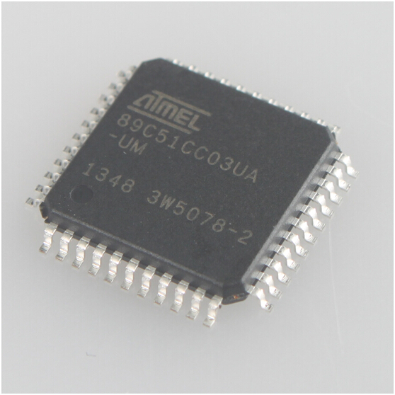
He used it to program keys for his Audi and I programmed 2 cars (Acura and Chrysler). It worked well. CK-100 needs tokens and it has only 1024 tokens. I cannot add tokens online, but buy an AT89C51CC03U NXP Fix Chip and directly replace the old board with the new one, then CLK100 will have more 1024 tokens.
I
wanted to use this tool to program Toyota chip G. But I was suggested
to use FVDI and after tested it can work. The shortage of CK-100 is that it cannot update online which is a little bit trouble, but it is cheap, so it deserves its value.
He used it to program keys for his Audi and I programmed 2 cars (Acura and Chrysler). It worked well. CK-100 needs tokens and it has only 1024 tokens. I cannot add tokens online, but buy an AT89C51CC03U NXP Fix Chip and directly replace the old board with the new one, then CLK100 will have more 1024 tokens.
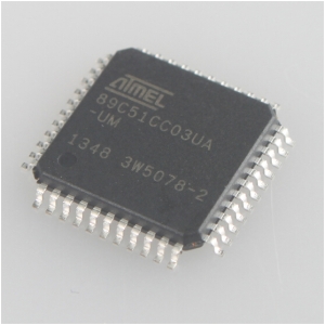
- NXP fix Chip for Ck-100 V99.99
Thursday, 22 May 2014
How to Reprogram a Car Key
Introduced in the 1990s, electronic keys can be programmed to your car's engine to offer extra convenience and security for your vehicle. These keys, also known as chip keys or transponder keys with CK-100 V99.99, are synced to your starter. Once they are programmed, they are the only keys that can start your car's ignition. You can reprogram lost signals from your driver's seat, in just minutes, as long as you have two programmed keys.
Enter your car with your two programmed keys and your new, unprogrammed key.
Insert the first programmed key into the ignition. Turn it to the "On" position, and then back to the "Off" position.
Remove the first key and insert the second key within five seconds.
Turn the second key "On" and then back "Off." Remove the key.
Insert the new key with VPC-100 within 10 seconds and turn it to the "On" position for one second. Return it to the "Off" position.
Wait for the security light to turn on and stay on for three seconds before removing the new key. The reprogramming is now finished.
Enter your car with your two programmed keys and your new, unprogrammed key.
Insert the first programmed key into the ignition. Turn it to the "On" position, and then back to the "Off" position.
Remove the first key and insert the second key within five seconds.
Turn the second key "On" and then back "Off." Remove the key.
Insert the new key with VPC-100 within 10 seconds and turn it to the "On" position for one second. Return it to the "Off" position.
Wait for the security light to turn on and stay on for three seconds before removing the new key. The reprogramming is now finished.
Friday, 9 May 2014
Review on SVDI VAG Commander

First things first, I can tell you that the tool really works. I have reset an Audi A6 service light and clear a 08 VW PASSAT 2.0airbag crash data with the tool. I also have successfully used it to program ECUs for a VW and a Skoda.
Besides, different from other VW diagnostic tools I have used before, SVDI is compatiable with both gasoline and diesel cars and trucks. That is just what I need.
About its quality and abaility, I have exchanged views with some mechanic friends who purchases SVDI from real stores. It is a lot cheaper than those SVDI commanders sold in auto repair shops, but according to my friends, it works as good as those ones.
Subscribe to:
Posts (Atom)